- English
- Türkçe
Joint R01 grant of Özgür Kocatürk (with Prof Levent Değertekin, Georgia Tech): “Acousto-optical RF Field sensors for safer diagnostic and interventional MRI”, in the amount of $1,296,611.00
Acousto-optical RF field sensors for safer diagnostic and interventional MRI
Although Magnetic Resonance Imaging (MRI) provides better soft tissue contrast and ionizing radiation free imaging environment compare to X-ray fluoroscopy, the use of MRI is limited as a medical imaging modality for interventional procedures due to the Radio Frequency Induced heating along the conductive medical devices and implants.
This project aims to develop a new set of tools for safer diagnostic (patients with metallic implants) and interventional MRI procedures. This effort includes significant innovations, from a miniaturized acousto-optical RF field sensor design, a novel assembly approach for active device tracking markers suitable for most available MRI compatible catheters, to in-situ multi-parameter E field sensors for local SAR measurement.
- Novel RF safe acousto-optical sensor structure: A novel sensor design uses piezoelectric transducers coupled to miniature RF antennae to directly convert the received RF field signals to sound waves in the embedded Bragg gratings in the optical fiber for accurate position tracking.
- Combined E/H field and temperature measurement for local in-situ SAR evaluation.
- Development of Universal “sleeve” based active markers for MRI compatible catheters: Many existing diagnostic catheters with different shapes optimized for different procedures are MRI compatible, but not visible under MRI. Active marker “sleeves” that contain the AO sensor optical fiber, conductive ink printed receiver coils and sensor connections will be formed and can be conformed to the shape of the catheter “on demand” simply by heat application before the procedures making them universally adaptable to all MRI compatible catheters.
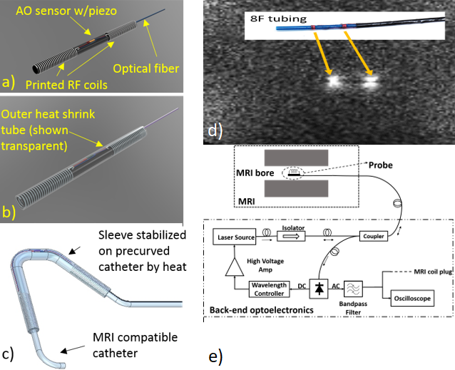
Figure 1. a) The AO sensor is fixed on the inner tubing which also has the conductive ink printed RF coil/antenna. b) A second het shrink tubing covers and protects the optical fiber and coils. c) After the sleeve is advanced on the catheter, it is fixed at desired location by applying heat using a heat gun. d) Image obtained from the catheter with two coils in MRI phantom using real time balanced steady state free precision (bSSFP) sequence with following scan parameters: flip angle: 90; repetition time: 471ms; echo time: 1.7ms ; FOV: 360 mm X 360 mm.) e) Schematic of the experimental setup to interface AO sensor with the MRI system.
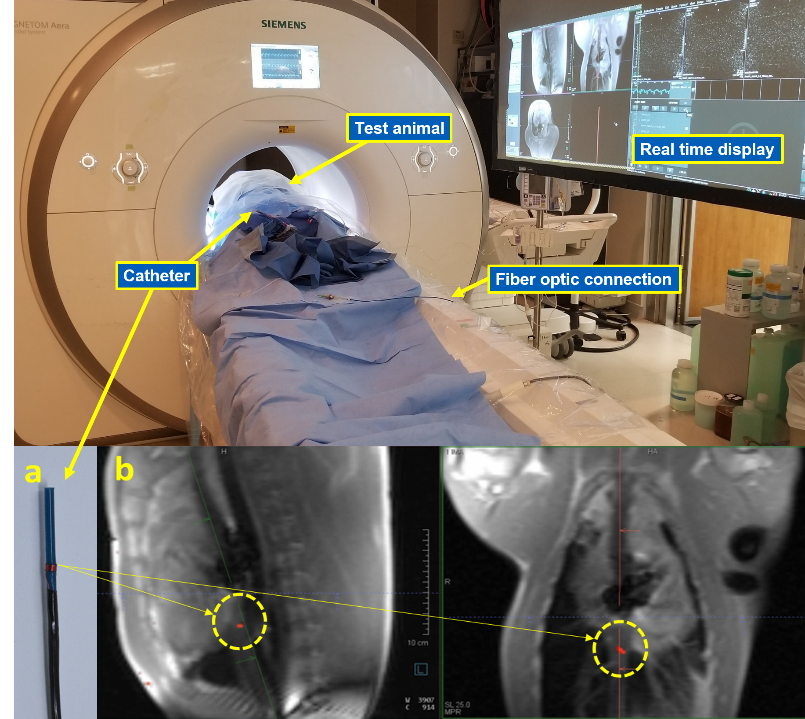
Figure 2. In-vivo imaging setup in the interventional MRI suite at NIH Clinical Center showing the test animal in the bore of the 0.55T MRI system with an 8F catheter (a) with marker coil inserted in the animal and connected to the AO sensor for readout. Overlad red markers are clearly seen in the image slices.
